Outdoor TV Antenna – Tech Talk
In previous articles, we “set the table” by explaining the concepts of TV channel frequencies and wavelengths, and also how TV signals travel from the broadcast station antenna to your home. We also discussed why TV antennas would optimally be positioned horizontally, although they can also function at times when aligned vertically.
One concept we mentioned earlier merits further discussion. Recall that we explained the wavelengths of TV broadcasts on channels 2 through 6 are quite large: The full wavelength for a TV signal on channel 6 (around 85 MHz) works out to be about 3.5 meters, or 11.5 feet. Yes, that would make for an extremely large antenna, and no, you won't find one that large for home TV reception.
Fact is; we don't need to use anything that large for reliable TV reception. Granted, the maximum amount of energy would be transferred from the broadcast station's electromagnetic wave to a TV antenna element at a full wavelength. But it would take up too much room! To save space, we can bend that antenna element into a loop, which wouldn't be nearly as obtrusive. We haven't changed its electrical length or resonance – just its form factor.
Even better, we can use a smaller fraction of a wavelength (one half) to enable successful reception. And we can also bend that half-wavelength element into a loop resembling a paper clip to conserve even more space. A half-wave loop antenna for channel 6 requires a little less than 3 feet in width, even though the electrical length is closer to 6 feet. This smaller antenna will still couple plenty of energy from the broadcast signal into our TV.
Indeed; the half-wave dipole loop was a classic design element for outdoor TV antennas for decades. It's called a dipole because it picks up RF signals from either side in a “figure eight” pattern. Dipoles can be made out of wire as well as tubular metal, and even today, a half-wave dipole made from TV ribbon antenna lead-in wire is included when you buy an FM receiver. Remember those vintage bow-tie antennas you've seen at flea markets, garage sales, and in electronic junk bins? Just another type of dipole. (Grab one, they work great!)
How can such small antennas possibly receive TV broadcasts on low-band and high-band VHF channels? Here's an analogy from the world of audio. Speakers use different-sized cones to reproduce sound, as the wavelengths of lower audio frequencies are longer than higher audio frequencies. A three-inch speaker may be fine for high frequency (treble) audio, but won't work very well for bass notes. The math suggests we might opt for an 8-inch speaker for bass. Or for even better bass reproduction, go with a 10-inch, 12-inch, or even a 16-inch speaker.
Yet, you can find plenty of small speakers that have good bass response, thanks to tricks with coils, acoustic chambers, and magnets. The same principle applies to antennas – their elements can be designed so that they achieve some degree of resonance, even though their physical size is much smaller. As you might intuit, this task becomes easier as we move higher in frequency and the wavelengths of TV channel frequencies shrink.
That's why a small, panel-style antenna can work so well for reception of UHF TV channels – a full wavelength at channel 25 (539 MHz), about mid-point in the UHF TV band, is just .55 meters, or 21.6 inches. A full-wave rectangular loop antenna for this frequency would measure just 5.4 inches on a side, which doesn't take up much space. However, these small panel antennas, installed indoors, will never be as efficient at coupling RF energy as large antennas mounted outside.
The good news is that we don't need a lot of signal to watch digital TV. The signals just have to be strong enough to overcome a given signal-to-noise (S/N) threshold, and voila – you have a perfect picture and sound. Fortunately, TV stations broadcast their signals with plenty of energy to ensure just about every viewer in their calculated coverage area (and many beyond) will be able to receive the signals using indoor or outdoor antennas. (Note that we said “just about every viewer,” as there will always be situations where reception is problematic, requiring a bit more problem solving.)
Now, let's turn our attention to choosing an outdoor antenna. As we did with indoor antennas, Job 1 is to determine which TV stations are active in your area and what TV channels they broadcast on. This is easily accomplished by going to Channelmaster.com/TVChannels and entering your postal zip code. You will then be shown a list of TV stations and channels, the distance from their transmitters to the center of your zip code.
When you go to a manufacturer's Web site to shop for an antenna, you'll notice there are several different antenna shapes and sizes for outdoor use. Some antennas are directional, with multiple elements of different lengths. Others have small elements arrayed against a large screen. And still others are simple loops with one straight element. Let's take a closer look.
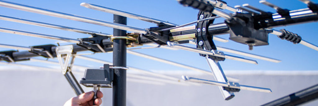
The largest TV antennas, known as “beam” or “yagi” antennas (after one its inventors, Dr. Hidetsugu Yagi) are directional antennas. These arrow-shaped antennas provide stronger received signal levels over simple omnidirectional antennas, a performance metric we can measure and define as “gain.” These antennas usually have one active (electrically-connected) driven element, which is a half-wave dipole or loop. There are also several shorter elements in front of the driven element, known as directors, and one or more longer elements behind the driven element, called reflectors. (Gain is a measurement of received signal levels when compared to those from a half-wave dipole.)
A common variant of this antenna is the log periodic TV antenna, which uses staggered elements of increasing length (reflectors and directors) and may have two or more active driven elements. Staggering the elements and varying their length helps the log periodic to work across a wider range of TV channels. It's also common to find combination VHF-UHF yagi and log periodic antennas, as neither antenna array impacts the receiving characteristics of the other and the combination saves installation space.
The next type of outdoor TV antenna – the screen variation mentioned earlier – has two or more active driven X-shaped antenna elements in a colinear array, spaced one-quarter wavelength away from the screen that serves as a reflector. While not as directional as a large log periodic antenna, these antennas have a pattern similar to one side of a dipole, and are useful for receiving UHF TV channels over medium to long distances. The antenna elements are too small for low-band or high-band VHF reception, although a strong local VHF station might still show up after a channel scan.
The last type of outdoor TV antenna is the smallest in terms of space requirements. It's the omnidirectional antenna, which resembles a circle or loop and is sometimes combined with a single rod-like antenna element. This antenna has little directivity and its coverage pattern more resembles that of a dipole. “Omnis” are best suited for outdoor installation in urban and suburban areas, particularly where the TV station signals are originating from two or more compass headings. They're also easier to mount against a wall or other surfaces.
To summarize; Channelmaster.com/TVChannels will get you in the ballpark, whichever TV antenna you eventually select. Keep in mind these are not hard-and-fast rules: If you have a line-of-sight, unobstructed path to the TV station tower, you'll have plenty of signal. Conversely, if you are in an urban area with lots of buildings and/or hills, a larger directional antenna might be required.